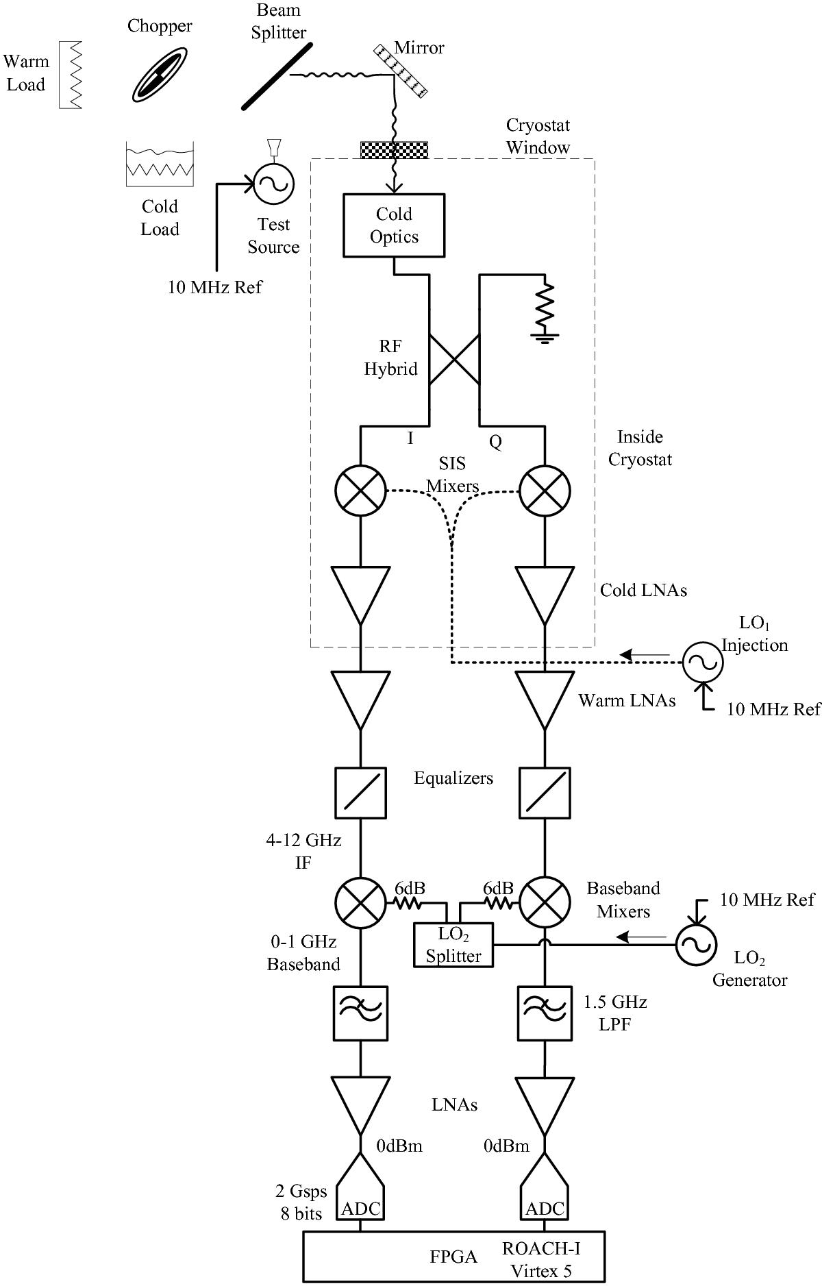
Fig. 2

Test setup block diagram: the front end of the receiver features an RF hybrid which splits the incoming signal into the I and Q channels. A first down-conversion to a 4–12 GHz IF band is performed using a pair of superconducting (SIS) mixers driven by an in-phase local oscillator (LO1). Cold and warm LNAs are used to boost the signal and then equalizers compensate the amplifiers gain slope. A second down-conversion to a 0–1 GHz baseband is performed using a pair of balanced mixers driven by an in-phase second local oscillator (LO2). Finally anti-aliasing filters and a last amplification stage are applied to reach optimal signal condition for the digitizers. The test source and the local oscillators are locked to the same 10 MHz reference to prevent frequency drift of the test tone during calibration. Recombination of the I and Q channels is done in the FPGA to produce the USB and LSB spectra.
Current usage metrics show cumulative count of Article Views (full-text article views including HTML views, PDF and ePub downloads, according to the available data) and Abstracts Views on Vision4Press platform.
Data correspond to usage on the plateform after 2015. The current usage metrics is available 48-96 hours after online publication and is updated daily on week days.
Initial download of the metrics may take a while.


