Fig. 15
Download original image
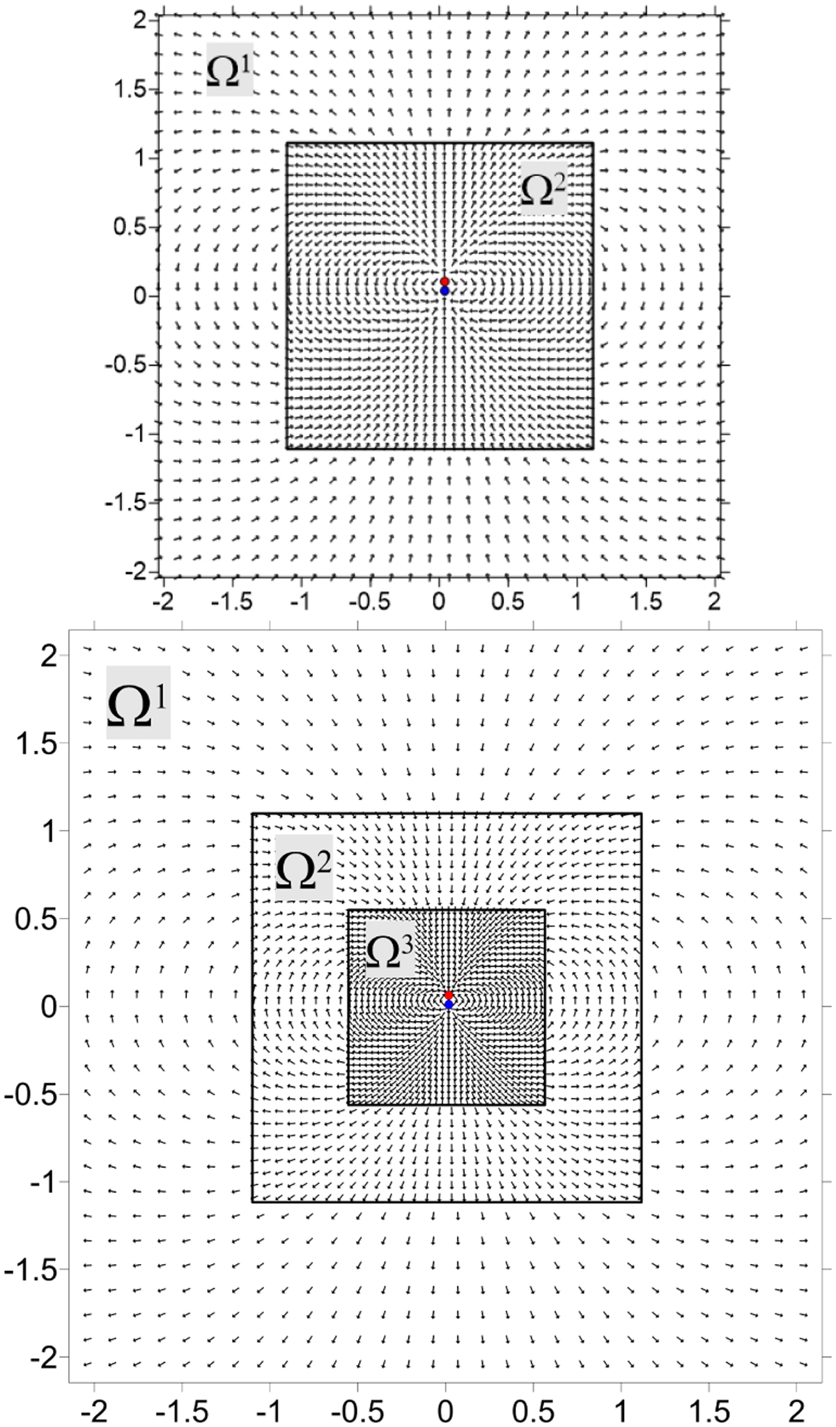
Electric field vectors of a dipole. The dipole is located at the center of the finest grid and is shown schematically by the red and blue circles. The modified convolution method is applied to construct the field (see Fig. 13 for comparison with the original method). The top panel presents the case of two nested grids, while the bottom panel corresponds to three nested grids. The black squares identify the grid interfaces. Note that the field is present and continuous across all nested grids Ω1, Ω2 and Ω3.
Current usage metrics show cumulative count of Article Views (full-text article views including HTML views, PDF and ePub downloads, according to the available data) and Abstracts Views on Vision4Press platform.
Data correspond to usage on the plateform after 2015. The current usage metrics is available 48-96 hours after online publication and is updated daily on week days.
Initial download of the metrics may take a while.