Fig. 3.
Download original image
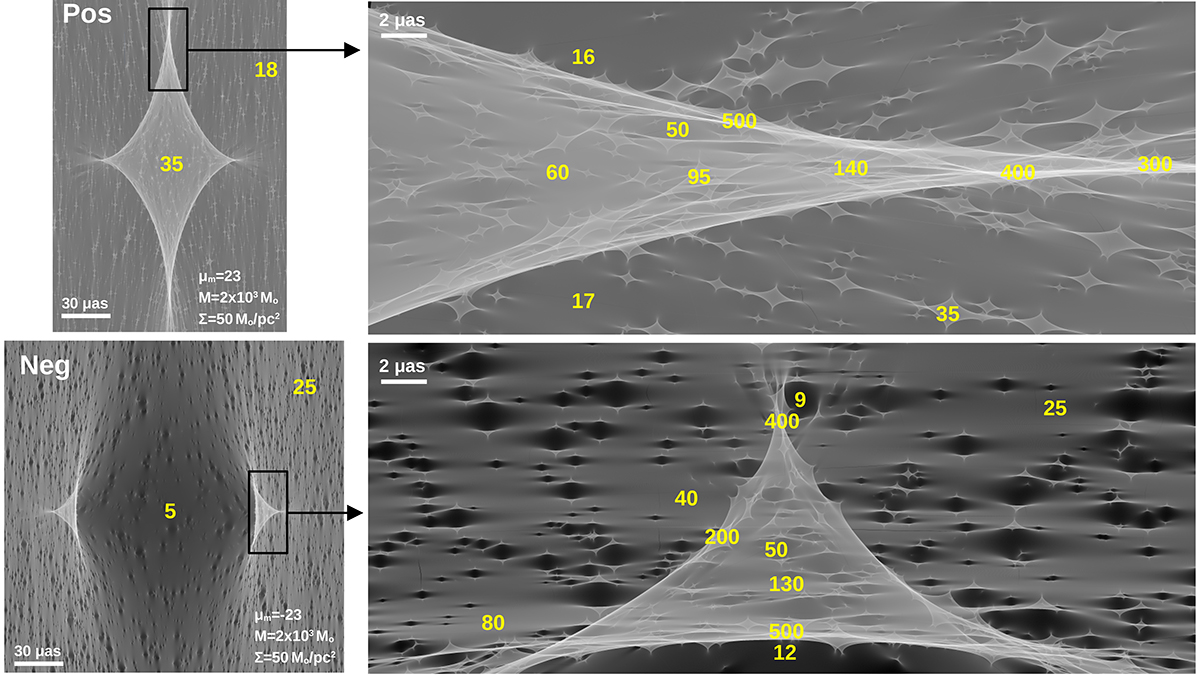
Simulated magnification maps of 3M lensing. Left panels. Shown as grayscale is the log of the magnification in the observer plane (caustics) around a millilens with mass 2 × 10³ M⊙, in two regions (positive and negative parities) where the macromodel magnification is ±23 and with a surface mass density of microlenses ![]() . The numbers in yellow indicate typical magnification values at these positions. For millilenses in regions with positive parity, outside the millicaustic region the magnification is typically below the macromodel value (but higher at the microcaustic regions). In the center of the millicaustic region, the typical magnification is ∼50% higher than the macromodel value. This situation is reversed in the region with negative parity. Right panels. Zoom-in around the regions of highest magnification at the millicaustics and marked with black rectangles in the left panel. Near the millicusps and millicaustics, microcaustics always overlap one another at magnifications greater than 100, hence maximizing the occurrence of microlensing events.
. The numbers in yellow indicate typical magnification values at these positions. For millilenses in regions with positive parity, outside the millicaustic region the magnification is typically below the macromodel value (but higher at the microcaustic regions). In the center of the millicaustic region, the typical magnification is ∼50% higher than the macromodel value. This situation is reversed in the region with negative parity. Right panels. Zoom-in around the regions of highest magnification at the millicaustics and marked with black rectangles in the left panel. Near the millicusps and millicaustics, microcaustics always overlap one another at magnifications greater than 100, hence maximizing the occurrence of microlensing events.
Current usage metrics show cumulative count of Article Views (full-text article views including HTML views, PDF and ePub downloads, according to the available data) and Abstracts Views on Vision4Press platform.
Data correspond to usage on the plateform after 2015. The current usage metrics is available 48-96 hours after online publication and is updated daily on week days.
Initial download of the metrics may take a while.