Fig. C.1
Download original image
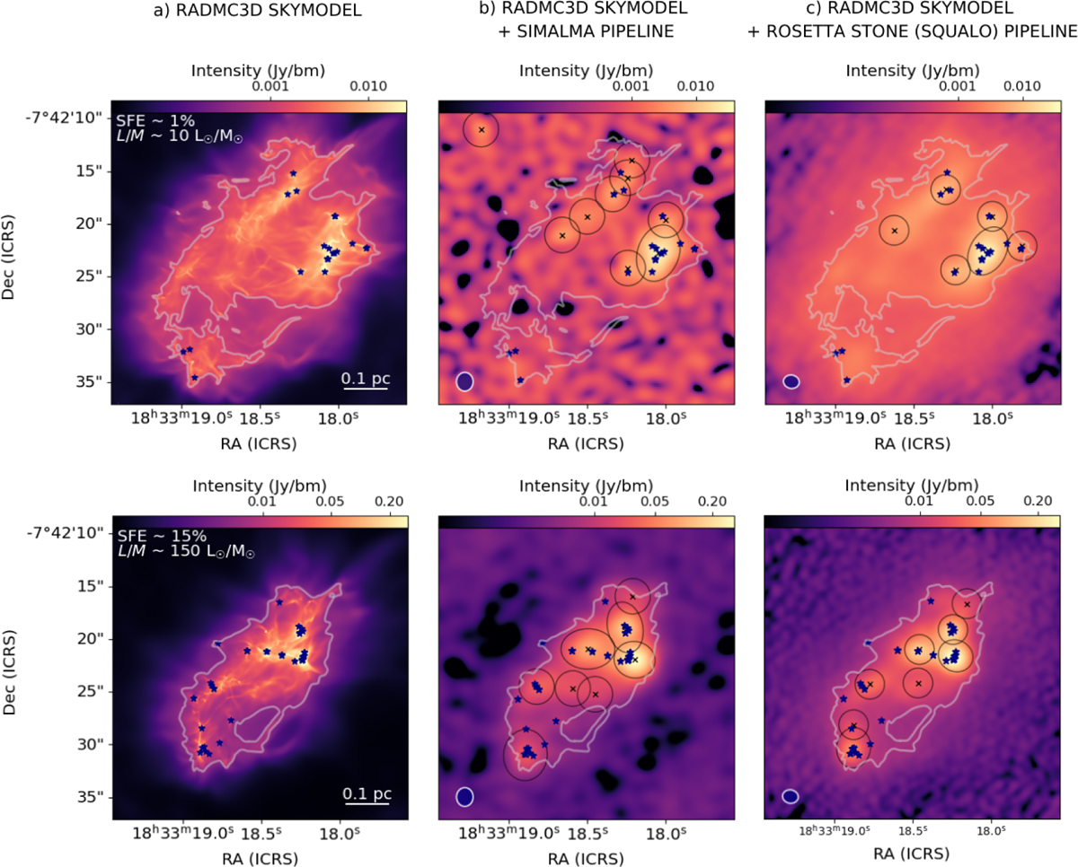
Post-processing pipeline comparison chart. Top to bottom: two evolutionary phases of the realization with Μ1000_μ 10_M7_S2. The snapshots correspond to ∼1 and 15% SFE, respectively. Left to right: a) synthetic surface brightness map after the radiative transfer; b) synthetic surface brightness map after the post-processing with the simalma pipeline of the CASA software; c) synthetic surface brightness map after the post-processing with the carefully tuned CASA-based Rosetta Stone pipeline, including the SQUALO tclean pipeline. The blue stars mark the positions of the sink particles. The gray contours mark the main emitting area in the RADMC-3D map and are overlaid on the post-processed maps for comparison. The black crosses and ellipses mark the centroids and the contours of the identified fragments. Source identification is performed as described in Section 2.3. In the RADMC-3D map we show the linear scale corresponding to 0.1 pc, while in the following maps we show the relative synthetic beam footprint.
Current usage metrics show cumulative count of Article Views (full-text article views including HTML views, PDF and ePub downloads, according to the available data) and Abstracts Views on Vision4Press platform.
Data correspond to usage on the plateform after 2015. The current usage metrics is available 48-96 hours after online publication and is updated daily on week days.
Initial download of the metrics may take a while.