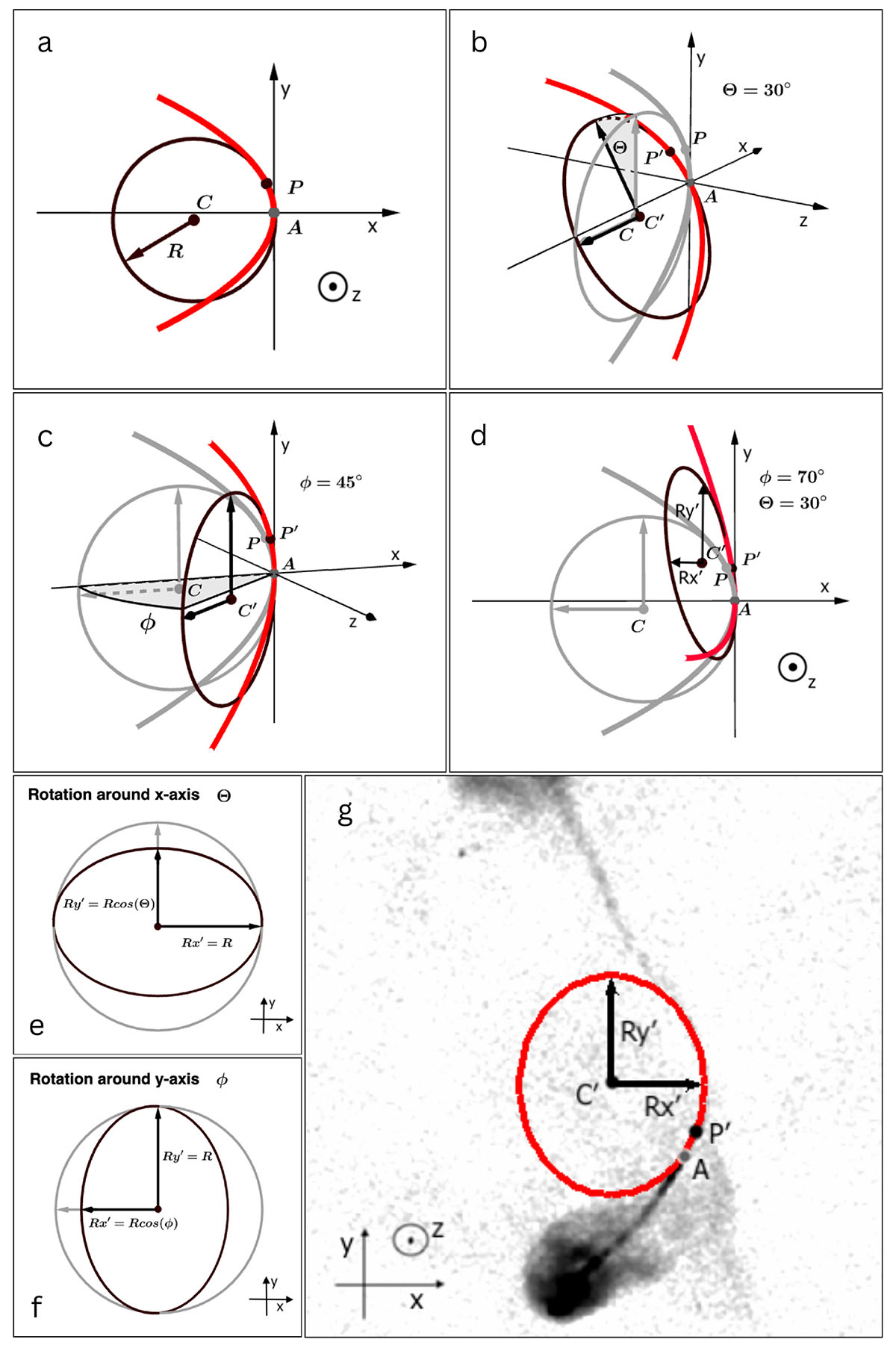
Fig. E.1.
Download original image
Illustration of projection effects due to WAT orientation (rotation). In panels a - f the geometry of the problem is visualized and explained step by step (follow the text of Appendix E), and in panel g the projection is analyzed for the real case - radio galaxy 10913. In all panels x-y plane corresponds to the plane of the sky, and z axis aligns with the LoS (pointing towards the observer). Markings A, P, C and R denote the radio core, the bending point, the center and the radius of the osculating circle at the bending point, respectively. P′ and C′ are the projected locations of P and C after rotation. Panel a: WAT lies entirely in the plane of the sky, R - radius of the osculating circle at the bending point, P, can be extracted directly from the observations; Panel b: WAT rotated by angle Θ around x-axis (tilted from the plane of the sky); gray indicates original jet position and osculating circle; Panel c: WAT rotated by angle ϕ around y-axis; Panel d: WAT rotated by Θ (x) and ϕ (y), projected osculating circle transformed into an ellipse; Panels e and f: Effect of Θ (e) and ϕ (f) rotations on x and y components of the projected R; Panel g: Observed radio morphology of WAT 10913, measuring projected x and y components of R.
Current usage metrics show cumulative count of Article Views (full-text article views including HTML views, PDF and ePub downloads, according to the available data) and Abstracts Views on Vision4Press platform.
Data correspond to usage on the plateform after 2015. The current usage metrics is available 48-96 hours after online publication and is updated daily on week days.
Initial download of the metrics may take a while.