Fig. 12.
Download original image
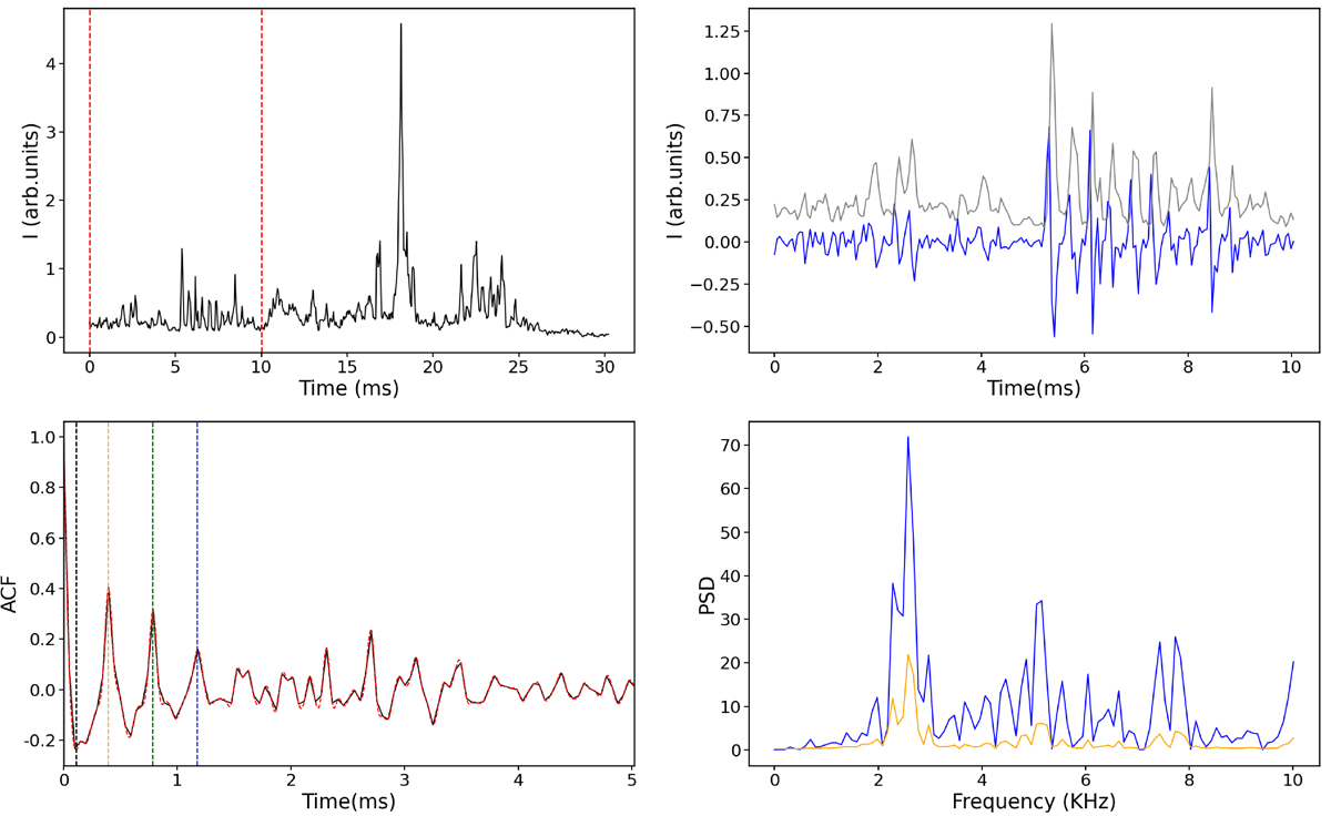
Example of the microstructure of PSR B0950+08. Top-left panel: Total intensity of a single pulse in the main pulse region; the dashed red area marks the window size of the first third of the main pulse. Top-right panel: Microstructure that satisfies the condition, corresponding to the dashed red region in the top-left panel. The gray and blue lines show the original data of the total intensity and the result after differencing, respectively. Bottom-left panel: ACF of the differenced signal; the solid black line is the initial ACF and the dashed red line represents the cubic spline interpolation of the ACF. Dashed black, orange, green, and blue vertical lines correspond to the first dip and the first, second, and third peaks in the spline-interpolated ACF, respectively. Bottom-right panel: Solid blue line represents the PSD of the differenced signal and the solid orange line represents the PSD of the ACF.
Current usage metrics show cumulative count of Article Views (full-text article views including HTML views, PDF and ePub downloads, according to the available data) and Abstracts Views on Vision4Press platform.
Data correspond to usage on the plateform after 2015. The current usage metrics is available 48-96 hours after online publication and is updated daily on week days.
Initial download of the metrics may take a while.