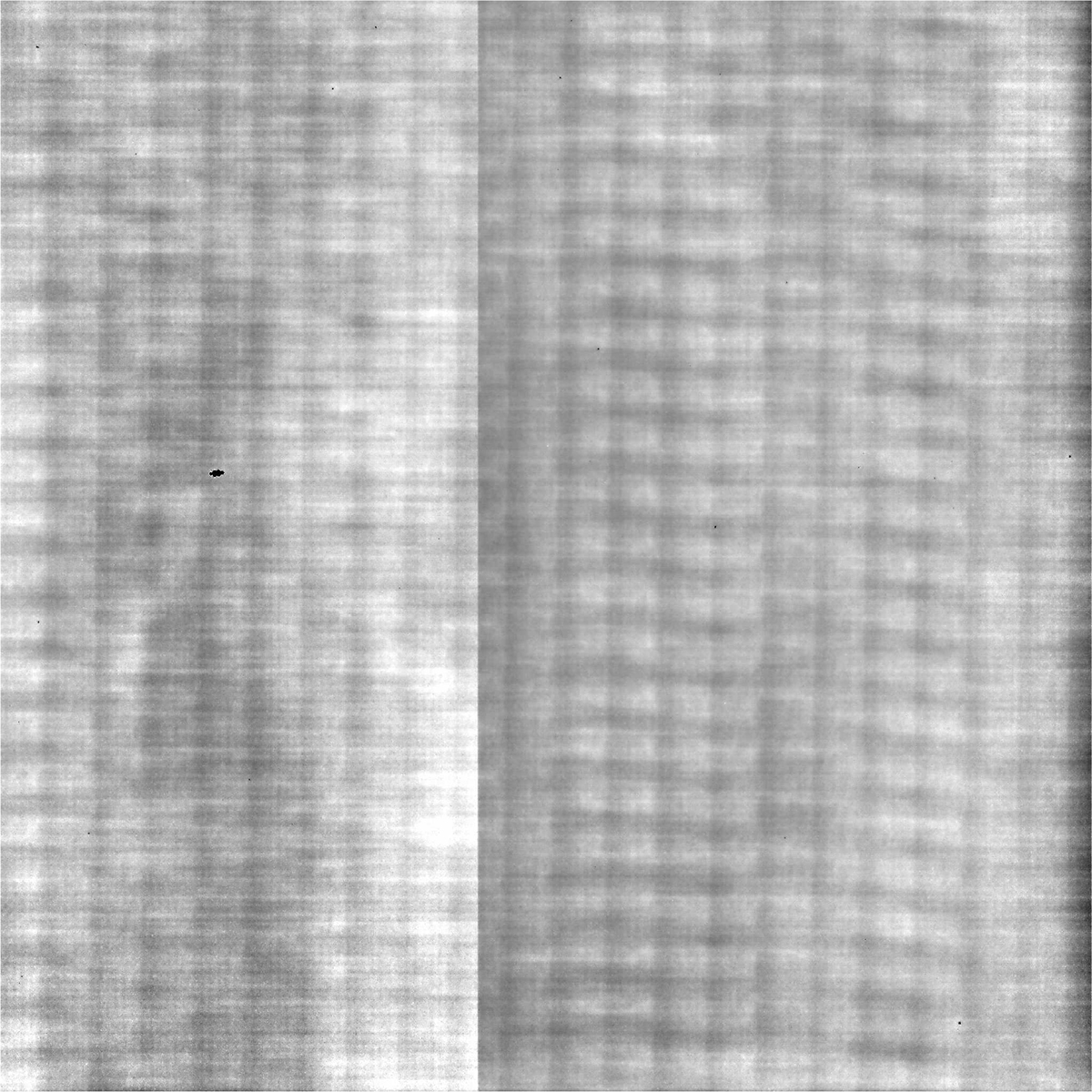
Fig. 15.
Download original image
Detector flat field derived from on-board calibration LEDs. The detector stitching line is visible as a column in the image, although it is aligned with the detector rows. This is due to the fact that from level L1, images are rotated by 90 degrees to orient solar north in the upward direction. The regular pattern is caused by the beam of the laser annealing used to activate the shallow p+ implant at detector backside.
Current usage metrics show cumulative count of Article Views (full-text article views including HTML views, PDF and ePub downloads, according to the available data) and Abstracts Views on Vision4Press platform.
Data correspond to usage on the plateform after 2015. The current usage metrics is available 48-96 hours after online publication and is updated daily on week days.
Initial download of the metrics may take a while.