| Issue |
A&A
Volume 703, November 2025
|
|
|---|---|---|
| Article Number | A213 | |
| Number of page(s) | 13 | |
| Section | Planets, planetary systems, and small bodies | |
| DOI | https://doi.org/10.1051/0004-6361/202555249 | |
| Published online | 18 November 2025 | |
Formation of np-Fe0 particles by H+ irradiation: Insight into space weathering on the moon and other airless bodies
1
Center for Lunar and Planetary Sciences, Institute of Geochemistry, Chinese Academy of Sciences,
Guiyang (Guizhou)
550081,
PR China
2
College of Earth and Planetary Sciences, University of Chinese Academy of Sciences,
Beijing
100049,
PR China
3
Center for Excellence in Comparative Planetology, Chinese Academy of Sciences,
Hefei (Anhui)
230026,
PR China
★ Corresponding authors: This email address is being protected from spambots. You need JavaScript enabled to view it.
; This email address is being protected from spambots. You need JavaScript enabled to view it.
Received:
22
April
2025
Accepted:
10
October
2025
Abstract
Context. Space weathering on airless bodies results in the formation of nanophase metallic iron (np-Fe0) particles, which will cause spectra darkening and reddening. However, the effects of temperatures and iron contents on np-Fe0 particles formation by H+ irradiation have not yet been well understood.
Aims. This research focuses on revealing how temperatures and iron contents affect the formation of solar wind-derived np-Fe0 particles.
Methods. We selected Chang’e 5 (CE-5) olivine and pyroxene grains with different iron contents and removed their native space weathering rim. H+ irradiation experiments were conducted at 87±2°C and room temperature, with an energy of 1.5 keV and a fluence of 1.0 × 10¹⁸ ion/cm2. Raman spectroscopy (Raman) was used to determine the mineral phases and the changes of chemical bonds before and after H+ irradiation. Fourier transform infrared spectroscopy (FTIR) was used to observe the Christiansen features (CFs), Reststrahlen bands (RBs), and the formation of water (OH/H2O) before and after H+ irradiation. Transmission electron microscopy (TEM) and dispersive X-ray spectroscopy (EDS) were used to observe the microstructure and composition of np-Fe0 particles, while electron energy loss spectroscopy (EELS) was used to analyze the valence states of iron.
Results. Np-Fe0 particles are only produced in the minerals with high iron contents after H+ irradiation at 87±2°C, rather than minerals with high iron contents but irradiated at room temperature or minerals with low iron content irradiated at 87±2°C. Compared with the np-Fe0 particles that are formed by impact melting, solar wind irradiation can effectively lower the formation temperature by about one magnitude.
Conclusions. This research provides direct evidence of np-Fe0 particle formation by H+ irradiation experiments and clarifies the necessary conditions, indicating solar wind irradiation is an effective way for np-Fe0 particles formation. The variation in iron contents and temperatures will help us to recognize the formation of np-Fe0 particles at different lunar regions and other airless bodies such as Mercury and asteroids, evaluating the effect of space weathering on remote sensing more precisely.
Key words: solar wind / minor planets, asteroids: general / Moon / planets and satellites: composition / planets and satellites: surfaces / planets and satellites: terrestrial planets
© The Authors 2025
 Open Access article, published by EDP Sciences, under the terms of the Creative Commons Attribution License (https://creativecommons.org/licenses/by/4.0), which permits unrestricted use, distribution, and reproduction in any medium, provided the original work is properly cited.
This article is published in open access under the Subscribe to Open model. This email address is being protected from spambots. You need JavaScript enabled to view it. to support open access publication.
1 Introduction
Space weathering, including micrometeorite bombardment, irradiation by solar wind and cosmic rays, and daily thermal heating, is the important process that alters the surfaces of airless bodies (Pieters et al. 2000; Hapke 2001; Noble 2004). Nanophase metallic iron (np-Fe0) particles, one of the products of space weathering, typically cause the spectral signatures of airless bodies to darken and redden (Cassidy & Hapke 1975; Taylor et al. 2001; Noble et al. 2007). Two primary formation mechanisms of np-Fe0 particles have been proposed: micrometeorite bombardment and solar wind irradiation. The former can be further divided into vapor deposition, direct decomposition, and disproportionation, whereas the latter primarily refers to reduction or sputtering by solar wind (Keller & McKay 1993; Dukes et al. 1999; Nakamura et al. 2011; Guo et al. 2022). Numerous simulation experiments and research on lunar samples have confirmed the np-Fe0 particle formation resulting from micrometeorite bombardment (Sasaki et al. 2001; Wu et al. 2017; Xu et al. 2023; Li et al. 2022a; Gu et al. 2025). However, the direct formation of np-Fe0 particles by solar wind irradiation has been long disputed (Hapke 2001; Pieters & Noble 2016).
To verify whether np-Fe0 particles can be produced directly by solar wind irradiation, a series of ion irradiation experiments have been conducted over several decades using different ions, energies, doses, fluxes, and minerals (Dukes et al. 1999; Carrez et al. 2002; Davoisne et al. 2008; Loeffler et al. 2009; Laczniak et al. 2021). Using X-ray photoelectron spectroscopy (XPS), previous studies detected the obvious metallic iron (Fe0) signal in irradiated samples, providing important evidence of the formation of np-Fe0 by solar wind irradiation (Dukes et al. 1999; Davoisne et al. 2008). However, for a long time, almost no np-Fe0 particles were observed directly in transmission electron microscopy (TEM) images of samples after irradiation. Until 2015, analysis of the irradiated orthopyroxene by electron energy loss spectroscopy (EELS) seemed to find the formation of np-Fe0 particles (Kuhlman et al. 2015). The latter experiment detected the metallic iron signal in olivine and pyroxene from the irradiated Murchison meteorite; however, no np-Fe0 particles were observed in their TEM images (Laczniak et al. 2021). Therefore, the factors that affect the formation of np-Fe0 particles by solar wind irradiation remain poorly understood.
The spatial differentiation of solar wind-formed np-Fe0 particles in the lamellae of Chang’e 5 (CE-5) pyroxene suggests the iron content can be an important factor affecting the formation of np-Fe0 particles in irradiated samples (Gu et al. 2022). In addition, the heating experiments also indicate the size of np-Fe0 particles will increase with the temperature (Thompson et al. 2017; Pang et al. 2024), indicating the temperature during H+ irradiation cannot be ignored either. To answer the question of how iron contents and temperatures affect the formation of np-Fe0 particles by solar wind irradiation, this research selected several olivine and pyroxene grains with different iron contents from the CE-5 sample and conducted H+ irradiation experiments at room temperature and 87±2°C (a temperature equivalent to the highest surface temperature of the CE-5 landing site), respectively. And a series of methods were used to analyze the formation of np-Fe0 particles by H+ irradiation.
 |
Fig. 1 CE-5 olivine and pyroxene grains were used for H+ irradiation experiments. The numbers at the middle of the marks represent the fayalite (Fa) and ferrosilate (Fs) values for olivine and pyroxene, respectively. ‘H’ represents the samples that were irradiated at a higher temperature, about 87±2°C, equating to the highest temperature of the CE-5 landing site, while ‘R’ means the samples were irradiated at room temperature. The green rectangles, red dots, and orange strips show the analysis locations of the FTIR and Raman, as well as the extraction sites of the FIB foil, respectively. Ol: Olivine; Px: pyroxene. |
2 Materials and methods
2.1 Sample preparation
The CE-5 lunar soil grains used in this study were collected and allocated by the China National Space Administration and labeled CE5C1000YJFM00303 and CE5C0400YJFM00504. These samples were stored in a glove box with a high-purity argon (Ar) atmosphere, and the contents of water and oxygen were less than 0.01 ppm. Under a binocular microscope in the glove box, dozens of grains were selected for scanning electron microscope (SEM) and dispersive X-ray spectrometer (EDS) analysis. A focusing ion beam (FIB) foil of the native space weathering rim was also extracted from an olivine grain to serve as the reference (Fig. A.1). Then, these samples were polished with 2000–5000 mesh sandpaper to remove natural space weathering rims and cleaned with acetone and ethanol in an ultrasonic cleaner. Next, these samples were baked at 120°C to remove the absorbed water and then analyzed by Raman spectroscopy (Raman) and Fourier transform infrared spectroscopy (FTIR). A total of eight samples of olivine and pyroxene with different iron content were prepared for H+ irradiation, named Ol-76-H, Ol-68-H, Ol-45-H, Px-52-H, Px-30-H, Px-27-H, Ol-87-R, and Px-61-R, respectively (Figs. 1, A.2, and Table A.1). All the sample preparation work was conducted at the Institute of Geochemistry, Chinese Academy of Sciences (IGCAS).
2.2 SEM and EDS analysis
Before H+ irradiation, to observe the microstructure and chemical composition of samples, the selected grains were stuck on the conductive tape and coated with a gold (Au) layer about 30 nm thick for SEM and EDS analysis. The backscattered electron imaging (BSE) and EDS analysis were done using a beam current of 0.8–1.6 nA and an accelerating voltage of 20–30 kV. Based on the SEM and EDS results, the FIB foil of the native space weathering rim was prepared with beam currents of 20 pA-4 nA and accelerating voltage of 5–30 kV. Then, these samples were polished and pressed into a customized indium (In) target with a purity of 99.99% for further H+ irradiation and analysis. After H+ irradiation, an FIB foil was prepared for each irradiated sample using the same method. All the FIB foils were preserved using vacuum sealing for further analysis. The work of SEM, EDS, and FIB was conducted at the IGCAS.
2.3 Raman spectroscopy analysis
To determine the mineral phases and the changes of chemical bonds before and after H+ irradiation, the Raman spectra of these samples were obtained by a Renishaw InVia laser Raman spectrometer at the IGCAS (Fig. A.3). The analysis parameters were as follows: laser wavelength of 532 nm, power of 0.4–2 W, spot size of 1 µm, exposure time of 30–60 s, spectral range of 100–4000 cm−1, and all spectra were accumulated twice to enhance the signal intensity.
2.4 FTIR spectroscopy analysis
To observe the Christiansen features (CFs), the Reststrahlen bands (RBs), and the formation of water (OH/H2O) before and after H+ irradiation, the FTIR spectra of these grains were acquired by a Thermo IS50 FTIR spectrometer at the IGCAS (Figs. A.4 and A.5). The reflectance spectra were obtained in the range of 8000–650 cm−1 (i.e., 1.25–l5.3 µm), with a spot size of 75 × 75 µm, spectral resolution of 4 cm−1, and 256 times scans. This analysis was conducted in a customized chamber. To reduce the interference from atmospheric water, before the analysis, the chamber was purged with dry air for more than 3 hours, and during the analysis, nitrogen gas was used for purging.
2.5 H+ irradiation experiments
To investigate whether H+ irradiation can form np-Fe0 particles directly, a series of H+ irradiation experiments were conducted using an ion implanter at the IGCAS. This instrument comprises several parts: an ion source, sample chamber, heating system, vacuum system, beam detection system, and control system (Fig. A.6). The energy of the implanted H+ was 1.5 keV, the flux was 2.42 × 10¹³ ions/cm2/s and the fluence of H+ was about 1.01 × 10¹⁸ ions/cm2, equivalent to 300 years of solar wind irradiation on the Moon (Zeng et al. 2021). Two groups of H+ irradiation experiments at different temperatures were conducted. The mark of ‘H’ was for samples irradiated at 87+2°C, which was similar to the highest surface temperature at the CE-5 landing site (Liu et al. 2022), while the mark of ‘R’ was for samples irradiated at room temperature.
2.6 TEM and EELS analysis
To observe the microstructure and composition of the samples, these FIB foils were characterized using a Talos F200S TEM (Thermo Fisher Scientific) at the Guangdong University of Technology and a Hitachi HF5000 aberration-corrected scanning transmission electron microscope (AC-TEM) at the Shanghai Institute of Ceramics, Chinese Academy of Sciences (SICCAS). The microstructure of each foil was determined by bright- and dark-field images, and the nanoscale crystal structure was identified by high-resolution (HR) TEM images. The compositions of the interest regions on the FIB foils were analyzed by EDS detectors that were installed on the Talos F200S and Hitachi HF5000, respectively. To acquire the valence states of iron, these FIB foils were analyzed by a Gatan GIF Quantum ER System Model 965 parallel EELS spectrometer attached to the Hitachi HF5000 AC-TEM at the SICCAS, operating with an accelerating voltage of 200 kV. The EELS spectral images were acquired in dual EELS mode with a probe current of 100 pA. The unirradiated area of each mineral was selected as an internal standard, and the np-Fe0 particle in the native space weathering rim was used as an external standard.
3 Results
3.1 Characteristics of Raman and FTIR spectra
Before H+ irradiation, the Raman spectra show olivines have strong Si-O stretching vibrations (νs) at 817 cm−1−820 cm−1 and Si-O antisymmetric stretching vibrations (νas) at 842 cm−1−848 cm−1 (Figs. 1a–d and Figs. A.3a–d). While pyroxenes have strong Si-O νs at 992 cm−1−1011 cm−1, Si-O bending vibrations (δ) at 662 cm−1−667 cm−1, and metal-oxygen bond vibrations (M–O) at 316 cm−1−394 cm−1 (Figs. 1e–1h and Figs. A.3e–h). After H+ irradiation, the olivine and pyroxenes show almost no changes in their peak positions, which suggests that the Raman shifts are not sensitive to space weathering primarily caused by solar wind irradiation.
Before H+ irradiation, the FTIR spectra show the CFs of olivines at 1053 cm−1−1082 cm−1; after H+ irradiation, the CFs are at 1059 cm−1−1082 cm−1, with the changes generally below the spectral resolution (<4 cm−1) (Figs. 1a–1d and Fig. A.4a). However, before H+ irradiation, the CFs of pyroxenes are at 1138 cm−1−1163 cm−1, while they shift to 1152 cm−1−1169 cm−1 after H+ irradiation (Figs. 1e–1h and Fig. A.4b). Notably, almost all these changes in CFs of olivines and pyroxenes move to the high wavenumbers (or short wavelengths) after H+ irradiation (Fig. A.4). The RBs of olivines and pyroxenes are 827 cm−1–1044 cm−1 and 877 cm−1−1104 cm−1, respectively. However, the RBs of these samples are almost unchanged after H+ irradiation (Fig. 1 and Fig. A.4). In addition, at 3000 cm−1−4000 cm−1, only sample Ol-76-H shows a faint water signal after H+ irradiation (Fig. A.5).
3.2 Damaged rims formed by H+ irradiation
After H+ irradiation, these samples have evident structurally damaged rims containing numerous vesicles (Fig. 2). According to the sizes of vesicles, the irradiated rim can be further divided into two distinct layers (Figs. 2a and 2b). For the representative olivine sample Ol-45-H, an outer layer with the thickness of 61–93 nm contains larger vesicles approximately ten nanometers in diameter; an inner layer with the thickness of 36–59 nm contains smaller vesicles approximately several nanometers in diameter (Fig. 2a). For the representative pyroxene sample Px-52-H, the thicknesses of the outer and inner layers are 69–120 nm and 30–60 nm, respectively (Fig. 2b). Whether it is Ol-45-H or Px-52-H, the EDS mapping results reveal oxygen is more depleted than iron in the whole irradiated rim, and both of them show more evident depletion in the vesicles than surrounding regions (Figs. 2c–2f). Underneath the inner layer of the irradiated rim is the minerals’ unirradiated area: all olivine samples, together with the pyroxene samples of Px-30-H and Px-27-H, have a relatively uniform composition. The unirradiated areas of samples Px-52-H and Px-61-R exhibit high-Fe (or low-Ca) and low-Fe (or high-Ca) lamellae, characterized by different contrasts and widths ranging from several to tens of nanometers (Figs. 2k and 2n).
3.3 Np-Fe0 particles produced by H+ irradiation
Notably, numerous nanoparticles are observed in samples Ol-76-H, Ol-68-H, Ol-45-H, and Px-52-H, while almost no nanoparticles are present in samples Px-30-H, Px-27-H, Ol-87-R, and Px-61-R (Figs. 2g-2n). These nanoparticles are mainly spherical in shape and mostly present in the inner layer of the irradiation rim. However, their distributions are different in olivine and pyroxene. In the olivine samples Ol-76-H, Ol-68-H, and Ol-45-H, nanoparticles are predominantly located near the boundary between the inner and outer layers, with no regular intermittent distribution differences observed in each sample (Figs. 2g–2i). However, for pyroxene sample Px-52-H, there are many nanoparticles only in the high-Fe lamellae; almost no nanoparticles are observed in the low-Fe (or high-Ca) lamellae (Fig. 2k), consistent with the distribution characteristics of np-Fe0 particles in CE-5 pyroxene (Gu et al. 2022). Statistical results show the average sizes of the nanoparticles in Ol-76-H, Ol-68-H, Ol-45-H, and Px-52-H were 2.47 nm, 2.33 nm, 2.29 nm, and 1.84 nm, respectively (Fig. A.7).
Several analysis results can determine whether these nanoparticles are np-Fe0 particles. First, when an EDS line scan passes through a nanoparticle, the atomic content of iron increases while oxygen shows the opposite trend, indicating that these nanoparticles are richer in iron than the surrounding material (Fig. 3a). Second, the HRTEM image reveals that these nanoparticles have fragile lattice structures, with lattice fringe spacing of 0.202–0.207 nm, which is consistent with α-Fe reported in previous researches (Gu et al. 2022; Guo et al. 2022; Li et al. 2022a; Xian et al. 2023) (Fig. 3b). Finally, EELS spectra reveal the valence states of iron in these nanoparticles (Figs. 3c–3i). The Fe L3 peak of Fe0 is close to that of Fe2+ at about 707.5 eV, which can be distinguished from the typical Fe L3 peak position of Fe3+ at about 709–710 eV (Guo et al. 2022; Li et al. 2022a). The nanoparticles in Ol-76-H (P1) and Ol-68-H (P2) show a common typical Fe L3 peak position at 707–707.85 eV, almost consistent with their unirradiated area with Fe2+ (P5 and P6) (Fig. 3g). The nanoparticle in Ol-45-H (P3) shows an Fe L3 peak at around 708.4 eV, suggesting that Fe3+ is likely present, possibly due to some oxidation that happened when preparing the sample (Fig. 3g). The EELS spectrum of the nanoparticle in Px-52-H (P4) shows a common Fe L3 peak at 707.75 eV, which is also near the internal standard of high-Fe (P8) or low-Fe lamellae (P9) with Fe2+ (Fig. 3g). Further away from the Fe L2 peak, different tail heights at 725–730 eV can be used to distinguish the Fe2+ and Fe0 (Xian et al. 2023). Similar to the tail features of np-Fe0 particles in the native space weathering rim (P10 and P11), the nanoparticles in Ol-76-H (P1) and Px-52-H (P4) both have higher tail features than their unirradiated areas with Fe2+ (P5 and P8), indicating that these nanoparticles are more likely Fe0 than Fe2+ (Figs. 3h, 3i and A.1). Based on the analysis results of the EDS, HRTEM, and EELS, these nanoparticles can be identified as np-Fe0 particles that were produced directly by H+ irradiation at 87±2°C, which is equivalent to the highest temperature at the CE-5 landing site.
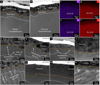 |
Fig. 2 Characteristics of CE-5 lunar minerals after H+ irradiation. (a, b) Overview of the irradiation-damaged rims with two different layers in the representative samples Ol-45-H and Px-52-H, respectively. (c, d) EDS mapping results of elements iron and oxygen for panel (a), respectively. (e, f) EDS mapping results of elements iron and oxygen for panel (b), respectively. (g–n) High-angle annular dark-field (HADDF) images of samples Ol-76-H, Ol-68-H, Ol-45-H, Ol-87-R, Px-52-H, Px-30-H, Px-27-H, and Px-61-R, respectively. The dashed yellow and white lines are the boundaries of two different layers, respectively. |
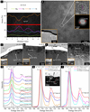 |
Fig. 3 Evidence of np-Fe0 particles produced by H+ irradiation. (a) Analysis result of EDS line scan for an np-Fe0 particle in Ol-76-H; the red line represents the location of EDS line scanning, and the dashed red circle is the location of the np-Fe0 particle. (b) HRTEM image of np-Fe0 particles in Ol-76-H. The lower left corner indicates the position where the main image (b) was acquired. The top right corner shows an enlarged image of the np-Fe0 particle and its corresponding fast Fourier transform (FFT) image. (c–i) Np-Fe0 particles in Ol-76-H, Ol-68-H, Ol-45-H, and Px-52-H identified by EELS. The minerals’ unirradiated areas were used for internal standards, and np-Fe0 particles in native space weathering rims were used for external standards to distinguish the valence states of iron. |
4 Discussion
4.1 Formation process of np-Fe0 particles by H+ irradiation
Early research suggests the direct chemical reduction of ferrous iron (Fe2+) by solar wind-implanted hydrogen is the main reason for np-Fe0 particles formation (Wehner 1961). However, this hypothesis is contrary to the results of the metallic iron signal in samples that were irradiated by noble gas ions, whose atoms are chemically inert and cannot act as reductants (Carrez et al. 2002; Davoisne et al. 2008). Although the chemical reduction can also make a great contribution to the formation of np-Fe0 particles in agglutinate, which can be illustrated as follows (Basu 2005):

These reactions not only produce np-Fe0 particles but also form abundant water, while the water detected in lunar impact glass seems to also support these reactions happening (Zhou et al. 2024). However, these reactions occur in the agglutinate glass, indicating that they took place under high-temperature conditions enough to produce melt (Hapke 2001; Basu 2005). While the highest temperature during this research was just 87+2°C, which is far lower than the formation temperature of agglutinate glass. In addition, although samples Ol-76-H and Ol-68-H contain the most obvious np-Fe0 particles, only a faint water signal was detected in sample Ol-76-H but not in sample Ol-68-H (Fig. A.5), further suggesting the chemical reduction cannot fully explain our results.
A mechanism of sputtered deposits by H+ irradiation is also suggested to be an important way for np-Fe0 particles formation (Cassidy & Hapke 1975). However, our polished samples have a relatively flat and smooth surface, which cannot retain the np-Fe0 particles during the irradiation process with high flux (Hapke 2001). In addition, an alternative mechanism of preferential sputtering of oxygen atoms by solar wind can also produce np-Fe0 particles (Pillinger et al. 1976). That means np-Fe0 particles should preferentially form in the outer layer of olivine and pyroxene grains with the highest iron contents. However, the fact that most np-Fe0 particles exist in the inner layer and almost no np-Fe0 particles are observed in samples Ol-87-R and Px-61-R seems to not support this hypothesis either, which may also be affected by the extremely high flux of H+ irradiation in this research. Therefore, a better theory is required to explain the formation process of np-Fe0 particles by H+ irradiation in this study.
H+ irradiation can cause the preferential sputtering of oxygen, leading to the loss of electrons (e-) and release of neutral oxygen (O) (Pillinger et al. 1976; Vorburger et al. 2014), creating a large quantity of excess electrons at the mineral surface. Because the Fe–O bond is weaker than the Si–O and Mg–O bonds (Dukes et al. 1999), it breaks more easily to form suspended Fe2+ under H+ irradiation, which can capture electrons to form iron atoms (Fe0). This process is particularly pronounced in olivine and pyroxene grains with high iron contents owing to the greater availability of Fe–O bonds. Meanwhile, remote-sensing observations also indicate that H+ can capture electrons to form neutral hydrogen (H) (McComas et al. 2009; Bhardwaj et al. 2015). The effects of ion irradiation on electrons of a solid target have also been well studied in material science (Zhang & Weber 2020). Previous heating experiments on lunar soil showed that the size of np-Fe0 particles increases with increasing temperature (Thompson et al. 2017), indicating that temperature can cause iron atoms to further aggregate and grow. In addition, abundant water was detected in plagioclase (Zeng et al. 2021; Zhou et al. 2022), which is almost without iron in composition, suggesting the combination of H+ with oxygen-dangling bonds could be a main mechanism for water formation rather than chemical reduction.
Therefore, the formation mechanism of np-Fe0 particles by H+ irradiation in this research can be simply illustrated as the following reactions and Fig. 4:

During the H+ irradiation process, oxygen is preferentially sputtered and Fe–O bonds destroyed, causing elemental depletion at the outermost surface. At the same time, oxygen ions (O2−) lost the electrons to form neutral oxygen, while Fe2+ and H+ captured these electrons to form iron atoms and neutral hydrogen, respectively. Meanwhile, the relatively high temperature (87±2°C) facilitates the aggregation of iron atoms and formation of np-Fe0 particles. Furthermore, a small amount of water can also be formed during the irradiation process, but the low content makes it not easy to detect by FTIR. Overall, the key points of this mechanism are that H+ irradiation caused electrons to redistribute on the mineral’s surface, while temperature facilitated the aggregation and growth of iron atoms.
This mechanism seems to suggest np-Fe0 particles are more likely formed at the outer layer due to the higher degree of destroyed Fe–O bonds by H+ irradiation; however, it will also destroy the lattice structure of np-Fe0 particles and hinder their further growth under the high flux irradiation. While the gradual damaged nature of irradiation rims for each olivine and pyroxene grain indicates that the energy of H+ declines from the surface to the interior; thus it is easier for iron atoms to cluster and form np-Fe0 particles in the inner layers rather than the outer layer. And as for the minerals’ unirradiated area, it is even less likely to form np-Fe0 particles at such a temperature (87±2°C). This mechanism also well explains why XPS can detect a metallic iron signal after irradiation by noble gas ions. Because these ions, like He2+, can also cause the redistribution of electrons on a mineral’s surface to form iron atoms. However, irradiation at room temperature suggests there is insufficient energy for iron atoms to aggregate to form np-Fe0 particles.
The solar wind is an ultra-high-speed plasma flow containing H+, He2+, and many electrons (Zhang et al. 2023), which means the formation of np-Fe0 particles by solar wind irradiation on the moon could be more complex. When lunar minerals like olivine and pyroxene are exposed to the space environment, they are continuously subjected to solar wind irradiation for a long time. During this period, not only H+ but also He2+ causes the breaking of the Fe–O bond and the redistribution of electrons. Meanwhile, abundant implanted solar wind electrons suggest Fe2+-captured electrons to form iron atoms (Fe0) can be more efficient. The high surface temperature on the moon and other post-heating events like micrometeorite impacts can all promote the formation and growth of np-Fe0 particles, making those formed entirely by the solar wind difficult to distinguish. Although some neutral hydrogen, oxygen, and water will be released, continuous exposure to solar wind can also lead to the accumulation of abundant water on the mineral surface.
4.2 Solar wind irradiation is an effective way to form np-Fe0 particles
Experiments using laser irradiation to simulate micrometeorite impact processes indicate that H+ irradiation is not essential for the formation of np-Fe0 particles (Sasaki et al. 2001 ; Weber et al. 2020; Xu et al. 2023). This has led to long-standing controversy over the importance of the solar wind to the formation of np-Fe0 particles. However, the np-Fe0 particles formed by laser irradiation usually require temperatures of about 1000°C, which is high enough to melt many minerals (Wu et al. 2017). Analysis of the np-Fe0 particles in microcraters of lunar soil also suggests the temperature will be even higher if the high pressure generated by micrometeorite impacts is taken into account (Li et al. 2022a). However, in this research, the actual temperature during the H+ irradiation process is only 87±2°C, which is at least an order of magnitude lower than the temperature required to produce np-Fe0 particles through laser irradiation or natural impact processes, indicating that solar wind irradiation is an effective way to form np-Fe0 particles.
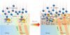 |
Fig. 4 Formation mechanism of np-Fe0 particles by H+ irradiation. |
4.3 Implications for space weathering on airless bodies
The direct formation of np-Fe0 particles by H+ irradiation at a temperature equivalent to the highest temperature of the CE-5 landing site has significant implications for our understanding of space weathering on the Moon and other airless bodies. Different iron contents and environmental temperatures are strongly correlated with the formation of np-Fe0 particles, which is meaningful for the discussion of space weathering at different compositional regions and the latitudes of the Moon. Lunar mare basalts usually have higher iron contents than those of lunar highland anorthosites (Lucey et al. 1995; Ohtake et al. 2009); therefore, solar wind irradiation is unlikely to form np-Fe0 particles in anorthosite-rich regions of the Moon. Minerals at the South Pole-Aitken composition anomaly (SPACA) region are usually with high iron contents, similar to those of basalts (Lucey et al. 1995; Moriarty Iii & Pieters 2018), suggesting that np-Fe0 particles formed by solar wind irradiation may also be prevalent in this region. Research on Apollo and CE-5 samples also shows that the contents or production rates of metallic iron increase with FeO abundance (Morris 1980; Lu et al. 2023), further indicating that the initial iron content is an important controller on the np-Fe0 particles formation.
There is a large difference in temperature across different latitudes of the lunar surface (Williams et al. 2017). The maximum daytime temperature on the equator is approximately 127°C (Vasavada et al. 2012), while in the polar illumination area, the maximum temperature is only −93°C (Paige et al. 2010; Williams et al. 2019). The CE-5 sample was collected from a mid-latitude area with a maximum temperature of approximately 87°C, while the Apollo samples were collected from a relatively low-latitude area with higher surface temperatures (Liu et al. 2022; Li et al. 2022b; Paige et al. 2010; Williams et al. 2017). This indicates the formation efficiency of np-Fe0 may be higher in Apollo samples with high iron contents owing to their higher temperature environment (Williams et al. 2017). However, lunar high-latitude regions, especially the polar illumination area, have a lower temperature, and the solar wind implantation angle is near horizontal (Paige et al. 2010; Li et al. 2018); thus the formation of np-Fe0 particles is likely to be inhibited, although this requires further investigation.
The space-weathering conditions of various airless bodies are obviously different. For example, the highest surface temperature on Mercury is higher than 430°C (Faure & Mensing 2007), while the maximum surface temperature of a main belt asteroid such as 21 Lutetia is only −28°C (Coradini et al. 2011). Mercury experiences a higher flux of solar wind irradiation and more intense micrometeorite impacts compared with the Moon and asteroids in the main belt (Pieters & Noble 2016). However, remote-sensing results show that the surface of Mercury has a low iron content with a mineral composition likely dominated by plagioclase and low-FeO pyroxene (Sprague et al. 2002; McClintock & Lankton 2007), which can also affect the formation of np-Fe0 particles that are produced by solar wind on Mercury. The surface composition of asteroid bodies such as Itokawa, Ryugu, Vesta, and Bennu is different from that of Mercury (McClintock & Lankton 2007; Nakamura et al. 2011; De Sanctis et al. 2012; Simon et al. 2020; Yokoyama et al. 2022; Hamilton et al. 2024). Owing to the low-temperature environment, the growth of np-Fe0 particles by solar wind irradiation may also be inhibited on the surfaces of such asteroids; however, given sufficient time, or aided by post-heating events, np-Fe0 particles can further grow.
5 Conclusions
In this research, several CE-5 olivine and pyroxene grains with different iron contents were polished and then used to conduct H+ irradiation experiments at different temperatures. The results show that np-Fe0 particles can directly form at 87±2°C in samples with high iron contents. While minerals with low iron contents that are irradiated at the same temperature, and those with high iron contents that are irradiated at room temperature, do not exhibit np-Fe0 particle formation. The H+ irradiation destroys the crystal structure and redistributes the electrons of target minerals, promoting Fe2+ capture electrons to form Fe0 and further growth to np-Fe0 particles at 87±2°C. The temperature of np-Fe0 particles generated by H+ irradiation in this research is much lower than the temperature of their formation in impact melting, indicating that solar wind irradiation is an effective way to form np-Fe0 particles. This research provides strong evidence that np-Fe0 particles can be formed directly by solar wind irradiation through the simulation experiment, which will help us to better understand the space weathering process on the moon and other airless bodies.
Acknowledgements
We thank all the staff of the Chang’e lunar exploration project for their hard work and CNSA for providing access to the lunar samples CE5C1000YJFM00303 and CE5C0400YJFM00504, Yanxue Wu for his assistance with Talos F200S TEM analysis, and Chenxi Zhu for his contributions to Hitachi HF5000 AC-TEM and EELS analysis. We thank Zhuang Guo and Ronghua Pang for many valuable suggestions on data analysis. We thank David Wacey, PhD, from Liwen Bianji (Edanz) (www.liwenbianji.cn) for editing the English text of a draft of this manuscript. This study was funded by the National Natural Science Foundation of China [grant numbers 42241104, 41931077]; the Youth Innovation Promotion Association, Chinese Academy of Sciences awards to Hong Tang [grant number Y2022099]; the Innovation and Development Fund of Science and Technology of Geochemistry, Chinese Academy of Sciences [grant number 2024-1]; and also supported by Guizhou Provincial 2019 Science and Technology Subsidies [grant number GZ2019SIG].
References
- Basu, A. 2005, J. Earth Syst. Sci., 114, 375 [Google Scholar]
- Bhardwaj, A., Dhanya, M., Alok, A., et al. 2015, Geosci. Lett., 2, 1 [Google Scholar]
- Carrez, P., Demyk, K., Cordier, P., et al. 2002, Meteorit. Planet. Sci., 37, 1599 [Google Scholar]
- Cassidy, W., & Hapke, B. 1975, Icarus, 25, 371 [NASA ADS] [CrossRef] [Google Scholar]
- Coradini, A., Capaccioni, F., Erard, S., et al. 2011, Science, 334, 492 [Google Scholar]
- Davoisne, C., Leroux, H., Frère, M., et al. 2008, A&A, 482, 541 [NASA ADS] [CrossRef] [EDP Sciences] [Google Scholar]
- De Sanctis, M., Ammannito, E., Capria, M., et al. 2012, Science, 336, 697 [NASA ADS] [CrossRef] [Google Scholar]
- Dukes, C., Baragiola, R., & McFadden, L. 1999, J. Geophys. Res.:Planets, 104, 1865 [Google Scholar]
- Faure, G., & Mensing, T. 2007, Introduction to Planetary Science (Springer) [Google Scholar]
- Gu, L., Chen, Y., Xu, Y., et al. 2022, Geophys. Res. Lett., 49, e2022GL097875 [Google Scholar]
- Gu, L., Lin, Y., Chen, Y., et al. 2025, Geochim. Cosmochim. Acta [Google Scholar]
- Guo, Z., Li, C., Li, Y., et al. 2022, Geophys. Res. Lett., 49, e2021GL097323 [Google Scholar]
- Hamilton, V., Keller, L., Haenecour, P., et al. 2024, in 55th Lunar and Planetary Science Conference (LPSC) [Google Scholar]
- Hapke, B. 2001, J. Geophys. Res.: Planets, 106, 10039 [NASA ADS] [CrossRef] [Google Scholar]
- Keller, L. P., & McKay, D. S. 1993, Science, 261, 1305 [NASA ADS] [CrossRef] [Google Scholar]
- Kuhlman, K. R., Sridharan, K., & Kvit, A. 2015, Planet. Space Sci., 115, 110 [Google Scholar]
- Laczniak, D., Thompson, M., Christoffersen, R., et al. 2021, Icarus, 364, 114479 [CrossRef] [Google Scholar]
- Li, S., Lucey, P. G., Milliken, R. E., et al. 2018, Proc. Natl. Acad. Sci. U.S.A., 115, 8907 [Google Scholar]
- Li, C., Guo, Z., Li, Y., et al. 2022a, Nat. Astron., 6, 1156 [NASA ADS] [CrossRef] [Google Scholar]
- Li, C., Hu, H., Yang, M.-F., et al. 2022b, Natl. Sci. Rev., 9, nwab188 [Google Scholar]
- Liu, J., Liu, B., Ren, X., et al. 2022, Nat. Commun., 13, 3119 [NASA ADS] [CrossRef] [Google Scholar]
- Loeffler, M., Dukes, C., & Baragiola, R. 2009, J. Geophys. Res.: Planets, 114 [Google Scholar]
- Lu, X., Chen, J., Ling, Z., et al. 2023, Nat. Astron., 7, 142 [NASA ADS] [Google Scholar]
- Lucey, P. G., Taylor, G. J., & Malaret, E. 1995, Science, 268, 1150 [NASA ADS] [CrossRef] [Google Scholar]
- McClintock, W. E., & Lankton, M. R. 2007, Space Sci. Rev., 131, 481 [Google Scholar]
- McComas, D., Allegrini, F., Bochsler, P., et al. 2009, Geophys. Res. Lett., 36 [Google Scholar]
- Moriarty Iii, D., & Pieters, C. 2018, J. Geophys. Res.: Planets, 123, 729 [Google Scholar]
- Morris, R. 1980, in Lunar and Planetary Science Conference, 11, Houston, TX, March 17-21, 1980, Proceedings. Vol. 2 (New York: Pergamon Press), 1697 [Google Scholar]
- Nakamura, T., Noguchi, T., Tanaka, M., et al. 2011, Science, 333, 1113 [NASA ADS] [CrossRef] [Google Scholar]
- Noble, S. K. 2004, Turning Rock into Regolith: The Physical and Optical Consequences of Space Weathering in the Inner Solar System (Brown University) [Google Scholar]
- Noble, S. K., Pieters, C. M., & Keller, L. P. 2007, Icarus, 192, 629 [CrossRef] [Google Scholar]
- Ohtake, M., Matsunaga, T., Haruyama, J., et al. 2009, Nature, 461, 236 [Google Scholar]
- Paige, D., Foote, M., Greenhagen, B., et al. 2010, Space Sci. Rev., 150, 125 [Google Scholar]
- Pang, R., Li, Y., Li, C., et al. 2024, Acta Geochim., 43, 774 [Google Scholar]
- Pieters, C. M., & Noble, S. K. 2016, J. Geophys. Res.: Planets, 121, 1865 [NASA ADS] [CrossRef] [Google Scholar]
- Pieters, C. M., Taylor, L. A., Noble, S. K., et al. 2000, Meteorit. Planet. Sci., 35, 1101 [CrossRef] [Google Scholar]
- Pillinger, C., Gardiner, L., & Jull, A. 1976, Earth Planet. Sci. Lett., 33, 289 [Google Scholar]
- Sasaki, S., Nakamura, K., Hamabe, Y., Kurahashi, E., & Hiroi, T. 2001, Nature, 410, 555 [NASA ADS] [CrossRef] [Google Scholar]
- Simon, A. A., Kaplan, H. H., Hamilton, V. E., et al. 2020, Science, 370, eabc3522 [Google Scholar]
- Sprague, A., Emery, J., Donaldson, K., et al. 2002, Meteorit. Planet. Sci., 37, 1255 [Google Scholar]
- Taylor, L. A., Pieters, C. M., Keller, L. P., Morris, R. V., & McKay, D. S. 2001, J. Geophys. Res.: Planets, 106, 27985 [Google Scholar]
- Thompson, M. S., Zega, T. J., & Howe, J. Y. 2017, Meteor. Planet. Sci., 52, 413 [Google Scholar]
- Vasavada, A. R., Bandfield, J. L., Greenhagen, B. T., et al. 2012, J. Geophys. Res.: Planets, 117 [Google Scholar]
- Vorburger, A., Wurz, P., Barabash, S., et al. 2014, J. Geophys. Res.: Space Phys., 119, 709 [Google Scholar]
- Weber, I., Stojic, A. N., Morlok, A., et al. 2020, Earth Planet. Sci. Lett., 530, 115884 [CrossRef] [Google Scholar]
- Wehner, G. 1961, ARS J., 31, 438 [Google Scholar]
- Williams, J.-P., Paige, D., Greenhagen, B., & Sefton-Nash, E. 2017, Icarus, 283, 300 [CrossRef] [Google Scholar]
- Williams, J.-P., Greenhagen, B., Paige, D., et al. 2019, J. Geophys. Res.: Planets, 124, 2505 [Google Scholar]
- Wu, Y., Li, X., Yao, W., & Wang, S. 2017, J. Geophys. Res.: Planets, 122, 1956 [NASA ADS] [CrossRef] [Google Scholar]
- Xian, H., Zhu, J., Yang, Y., et al. 2023, Nat. Astron., 7, 280 [Google Scholar]
- Xu, J., Mo, B., Wu, Y., et al. 2023, A&A, 672, A115 [NASA ADS] [CrossRef] [EDP Sciences] [Google Scholar]
- Yokoyama, T., Nagashima, K., Nakai, I., et al. 2022, Science, 379, eabn7850 [Google Scholar]
- Zeng, X., Tang, H., Li, X., et al. 2021, Earth Planet. Sci. Lett., 560, 116806 [CrossRef] [Google Scholar]
- Zhang, Y., & Weber, W. J. 2020, Appl. Phys. Rev., 7 [Google Scholar]
- Zhang, H., Cao, J., Lin, Y., et al. 2023, Space: Sci. Technol., 3, 0060 [Google Scholar]
- Zhou, C., Tang, H., Li, X., et al. 2022, Nat. Commun., 13, 5336 [Google Scholar]
- Zhou, C., Mo, B., Tang, H., et al. 2024, Sci. Adv., 10, eadl2413 [Google Scholar]
Appendix A Supplementary information
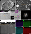 |
Fig. A.1 The native space weathering rim of a representative sample before the polishing process. (a-b) SEM image and an enlarged area of the representative sample. The FIB foil site is shown with a yellow rectangle. (c-e) TEM, HRTEM, and the corresponding FFT image of the native space weathering rim. (f) HADDF image of native space weathering rim and corresponding EDS mapping results. The sample after the polishing process is named Ol-45-H. |
Chemical composition of samples analysis by EDS
 (A.1)
(A.1)
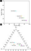 |
Fig. A.2 Chemical composition of CE-5 olivine and pyroxene samples used in this research. |
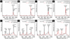 |
Fig. A.3 Raman spectra of CE-5 samples before and after H+ irradiation. (a-d) Raman spectra of olivine. (e-h) Raman spectra of pyroxenes. The black and red curves are the Raman spectra of the samples before and after H+ irradiation, respectively. |
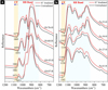 |
Fig. A.4 The CFs and RBs of CE-5 samples before and after H+ irradiation. (a) FTIR spectra of olivines. (b) FTIR spectra of pyroxenes. |
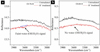 |
Fig. A.5 Characteristics of water signal in H+-irradiated samples Ol-76-H and Ol-68-H. |
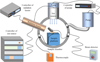 |
Fig. A.6 Diagram of the irradiation equipment. |
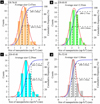 |
Fig. A.7 Size distributions of np-Fe0 particles in H+ irradiated samples. (a-d) The sizes of np-Fe0 particles in Ol-76-H, Ol-68-H, Ol-45-H, and Px-52-H, respectively. |
All Tables
All Figures
|
Fig. 1 CE-5 olivine and pyroxene grains were used for H+ irradiation experiments. The numbers at the middle of the marks represent the fayalite (Fa) and ferrosilate (Fs) values for olivine and pyroxene, respectively. ‘H’ represents the samples that were irradiated at a higher temperature, about 87±2°C, equating to the highest temperature of the CE-5 landing site, while ‘R’ means the samples were irradiated at room temperature. The green rectangles, red dots, and orange strips show the analysis locations of the FTIR and Raman, as well as the extraction sites of the FIB foil, respectively. Ol: Olivine; Px: pyroxene. |
| In the text | |
|
Fig. 2 Characteristics of CE-5 lunar minerals after H+ irradiation. (a, b) Overview of the irradiation-damaged rims with two different layers in the representative samples Ol-45-H and Px-52-H, respectively. (c, d) EDS mapping results of elements iron and oxygen for panel (a), respectively. (e, f) EDS mapping results of elements iron and oxygen for panel (b), respectively. (g–n) High-angle annular dark-field (HADDF) images of samples Ol-76-H, Ol-68-H, Ol-45-H, Ol-87-R, Px-52-H, Px-30-H, Px-27-H, and Px-61-R, respectively. The dashed yellow and white lines are the boundaries of two different layers, respectively. |
| In the text | |
|
Fig. 3 Evidence of np-Fe0 particles produced by H+ irradiation. (a) Analysis result of EDS line scan for an np-Fe0 particle in Ol-76-H; the red line represents the location of EDS line scanning, and the dashed red circle is the location of the np-Fe0 particle. (b) HRTEM image of np-Fe0 particles in Ol-76-H. The lower left corner indicates the position where the main image (b) was acquired. The top right corner shows an enlarged image of the np-Fe0 particle and its corresponding fast Fourier transform (FFT) image. (c–i) Np-Fe0 particles in Ol-76-H, Ol-68-H, Ol-45-H, and Px-52-H identified by EELS. The minerals’ unirradiated areas were used for internal standards, and np-Fe0 particles in native space weathering rims were used for external standards to distinguish the valence states of iron. |
| In the text | |
|
Fig. 4 Formation mechanism of np-Fe0 particles by H+ irradiation. |
| In the text | |
|
Fig. A.1 The native space weathering rim of a representative sample before the polishing process. (a-b) SEM image and an enlarged area of the representative sample. The FIB foil site is shown with a yellow rectangle. (c-e) TEM, HRTEM, and the corresponding FFT image of the native space weathering rim. (f) HADDF image of native space weathering rim and corresponding EDS mapping results. The sample after the polishing process is named Ol-45-H. |
| In the text | |
|
Fig. A.2 Chemical composition of CE-5 olivine and pyroxene samples used in this research. |
| In the text | |
|
Fig. A.3 Raman spectra of CE-5 samples before and after H+ irradiation. (a-d) Raman spectra of olivine. (e-h) Raman spectra of pyroxenes. The black and red curves are the Raman spectra of the samples before and after H+ irradiation, respectively. |
| In the text | |
|
Fig. A.4 The CFs and RBs of CE-5 samples before and after H+ irradiation. (a) FTIR spectra of olivines. (b) FTIR spectra of pyroxenes. |
| In the text | |
|
Fig. A.5 Characteristics of water signal in H+-irradiated samples Ol-76-H and Ol-68-H. |
| In the text | |
|
Fig. A.6 Diagram of the irradiation equipment. |
| In the text | |
|
Fig. A.7 Size distributions of np-Fe0 particles in H+ irradiated samples. (a-d) The sizes of np-Fe0 particles in Ol-76-H, Ol-68-H, Ol-45-H, and Px-52-H, respectively. |
| In the text | |
Current usage metrics show cumulative count of Article Views (full-text article views including HTML views, PDF and ePub downloads, according to the available data) and Abstracts Views on Vision4Press platform.
Data correspond to usage on the plateform after 2015. The current usage metrics is available 48-96 hours after online publication and is updated daily on week days.
Initial download of the metrics may take a while.